How to check a relay switch
The Video Course teaches you everything about modern cars.
If a component that is fed with electricity through a relay (See How car electrical systems work ) terminal of the battery to the feed terminal on the component, thereby bypassing the relay and supply wiring.
If the component still does not work, it is faulty; if it works, then the supply is faulty and the fault will be in the relay or the connections to it.
Trace the supply wire back to find the relay — this is a small metal or plastic box which usually has four spade terminals and is located near the battery .
Check that a supply wire has not become detached from a terminal. Check each terminal for corrosion, especially the thin wire from one terminal which goes to earth on the car body — probably fastened under a screw or bolt near by.
Remove the screw and clean the terminal and the underside of the screw head.
The relay has one thick cable coming from the positive (+) pole of the battery. A second thick cable goes from the relay to the component. A thin wire runs from the control switch on the steering column or dashboard , while a second thin wire goes to an earthing point.
Use a circuit tester to check whether current is reaching the relay. Clip one wire to earth on an unpainted part of the car and probe the feed terminal on the relay.
If the tester lights, there is power arriving at the relay. If it does not light, check the connection at the battery.
If the tester lights, turn on the switch inside the car which controls the component and use the tester again to check for power on the thin wire leading from the switch to the relay.
If there is no power, use the lamp to check the input and output terminals on the switch. This will tell you if current is reaching the switch from the battery, and if the switch is passing the current when switched on.
If there is power at the relay, use the tester on the relay earth terminal the second thin wire. No current flowing to earth means that the relay unit is faulty and must be replaced.
If the relay is earthing properly, leave the control switch on and use the tester on the relay terminal which feeds the component.
If there is no power, the fault is in the relay again — probably the contacts are burned or stuck in the open position.
Burned contacts can also fuse together, so that they stick in the closed position, so the component does not switch off. In either case, replace the relay.
Some relays have small pin connectors and plug into an enclosed socket.
Remove the suspect relay and replace it with another of the same type. If the component works, the original relay is faulty.
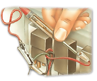
If the component still does not work, check the terminals in the base of the relay connector block with the circuit tester probe. For the tester bulb to light there must be a good contact at the test points. That is the reason for the sharp probe, and for the sharp teeth on the clip.
The probe is useful for poking under the plastic covers of spade terminals and snap connectors without the need to disconnect them.
Sometimes it is convenient to use the probe to prick through the insulation of a wire if other access is difficult.
Apart from the circuit tester, another useful aid is a test lead — a 10 ft (3m) length of wire with a crocodile clip at each end. This allows you to make direct connections from the battery to components which are some distance away, for example the rear lights, rear-mounted electric fuel pump and fuel-tank sender units.
A typical charging circuit
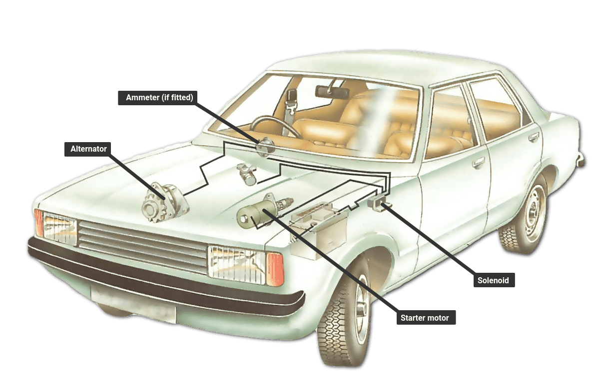
The battery is earthed to the body by a short, heavy cable or by a braided wire strap.
On most cars the negative battery terminal is earthed. From the positive terminal another heavy cable goes to the starter solenoid switch, which feeds current to the starter along a third heavy cable.
A wire leads from the live side of the solenoid (not through the switch itself) to the ignition switch .
Another wire leads from the live side of the solenoid to the ammeter (if fitted) on the instrument panel. Thus, the ammeter is always live, and always shows whether any power is being discharged. This circuit is then completed to the generator , so that current in the opposite direction causes the ammeter to show how much the battery is being charged.
From a point after the ammeter, another wire (not shown) goes to the lighting switches and to the fuse box, where it supplies power for circuits not controlled by the ignition switch.
An ignition-controlled circuit
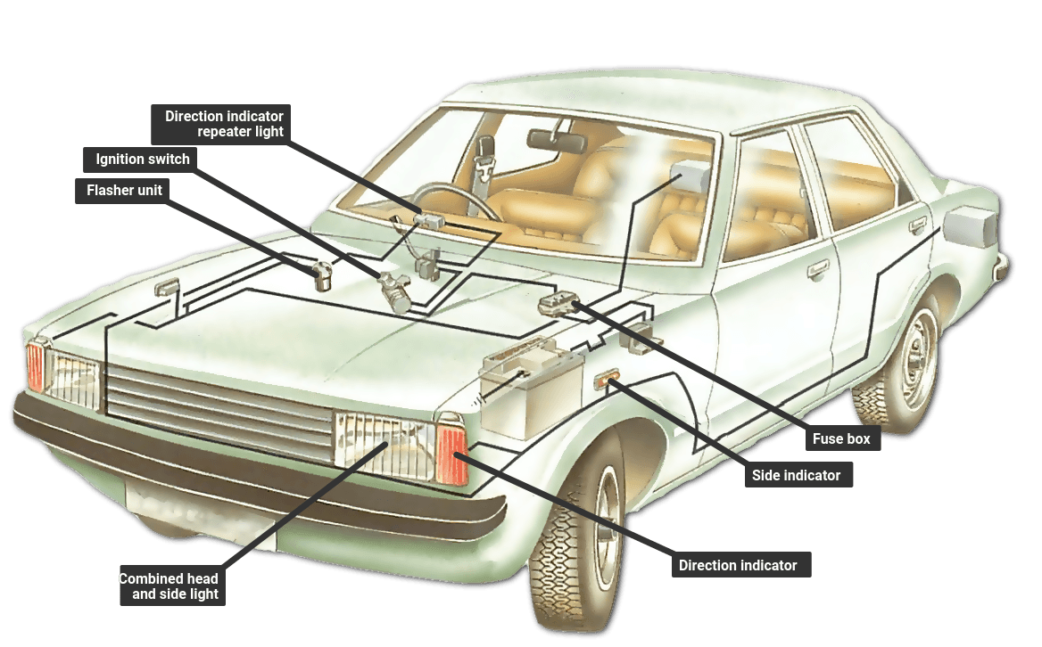
If the car circuits could be accidentally left 'live' when the car is not running, the battery would be discharged unnecessarily. For this reason, most circuits are operated through the ignition switch. (The exceptions are those which might be needed for safety - chiefly headlamps, sidelights and emergency flashers.)
From the ignition switch a plain wire runs to the fuse box, where it is connected to the fuses of all those circuits which come on with the ignition.
From each fuse a plain wire runs to each of the circuits, picking up a trace colour after its first connection.

The Ultimate Car Mechanics video course
Learn everything about modern cars from our new video series.
Learn more >-
We build a Mazda MX5 Miata from scratch
We start by tearing down and then rebuilding the whole car.
-
Every part explained
There's ridiculous detail on every part. Clearly and easily explained.
-
All modeled in 3D
We've created the most detailed 3D model ever produced so we can show you everything working.
Super detailed explanations in the video course
15 hours of pro-quality, HD content with subtitles
The
video
course
Bonus: Dismantling the engine

Engine Block
Crankshaft

Tools: Using a tap set
Using an engine stand

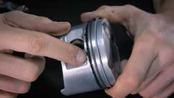
The Pistons