Fitting an electric fan to a side radiator
The Video Course teaches you everything about modern cars.
Fitting an electric, thermostatically controlled fan in place of the mechanical, engine -driven type can save you fuel and allow you to regain engine power normally wasted in constantly driving the fan.
This article shows you how to fit an electric fan to a car that has a transverse engine with a side-mounted radiator - such as the Mini.
Restricted space
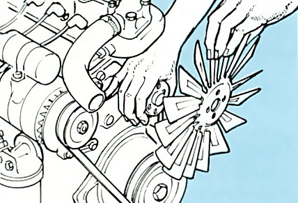
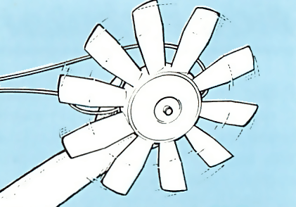
The compactness of the engine compartment in this type of car means that there is a restricted amount of space around the radiator area and you need to fit a special type of electric fan - a suction fan.
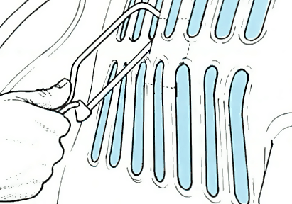
Also as a result of restricted space, the fan is mounted in a different way. Instead of being attached to the radiator itself, it is fitted to the inner wing, outboard of the radiator. Hence it sucks. rather than blows air through the radiator. You need to cut a hole in the cowling that covered the mechanical fan to allow air, which is forced into the engine bay when the car is travelling, to help cool the radiator so that the fan doesn't have to work all the time the engine is running.
Fitting
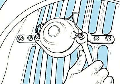
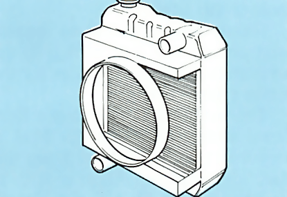
It is a little more complicated to fit a fan to a side-mounted radiator than to a front-mounted one. You need to do some cutting and drilling to the inner wing and you also have to remove the radiator to cut out the hole in the cowling.
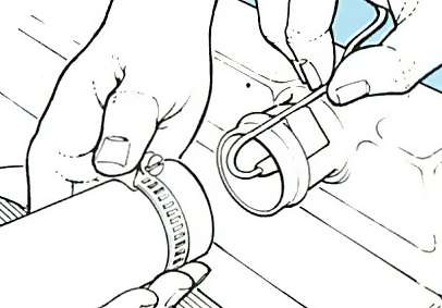
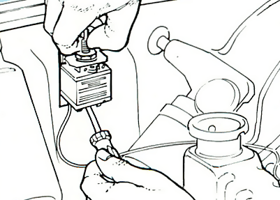
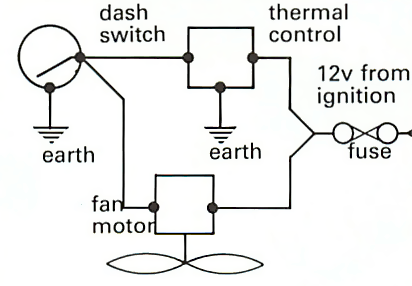
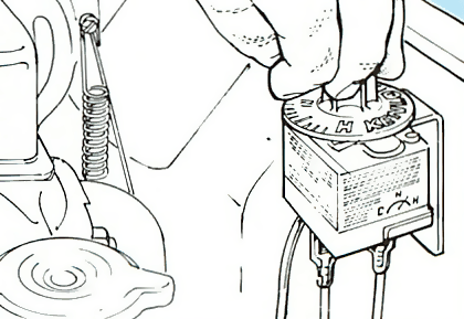
Fitting the temperature sensor and control unit and wiring up the system is much the same as for the other types of fan.
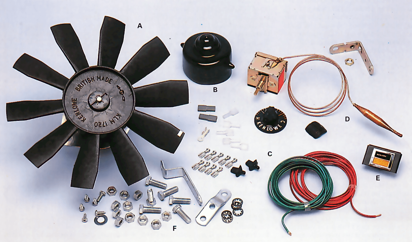
The procedure for fitting a Kenlowe suction fan to a BL Mini is covered overleaf. When fitting this fan, or another maker's fan, to another model of car, you should refer to the kit fitting instructions for any additional or alternative instructions.

The Ultimate Car Mechanics video course
Learn everything about modern cars from our new video series.
Learn more >-
We build a Mazda MX5 Miata from scratch
We start by tearing down and then rebuilding the whole car.
-
Every part explained
There's ridiculous detail on every part. Clearly and easily explained.
-
All modeled in 3D
We've created the most detailed 3D model ever produced so we can show you everything working.
Super detailed explanations in the video course
15 hours of pro-quality, HD content with subtitles
The
video
course
Bonus: Dismantling the engine

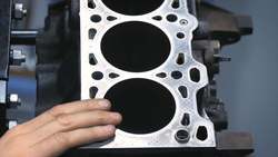
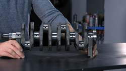
Engine Block
Crankshaft
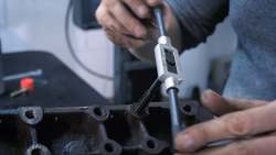
Tools: Using a tap set
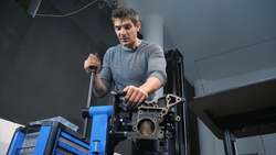
Using an engine stand
The Pistons