From our insanely detailed guide:
Crankshaft
The combustion of fuel shoots the piston straight down the cylinder, it’s the job of the crankshaft to convert this linear motion into rotation - basically by swinging around and pushing the piston back up the cylinder.
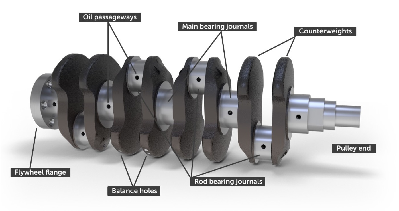
The terminology of a crankshaft is quite specialist, so we’ll start with naming a few parts. A journal is the part of a shaft that rotates inside a bearing. As can be seen above, there are two types of journal on a crankshaft - the main bearing journals form the axis of rotation for the crankshaft, and the connecting rod journals are secured to the ends of the connecting rods, which run up to the pistons.
For extra confusion, the connecting rod journals are abbreviated to rod journals and also commonly called crank pins , or big-end journals . The rod journals are connected to the main journals by webs .
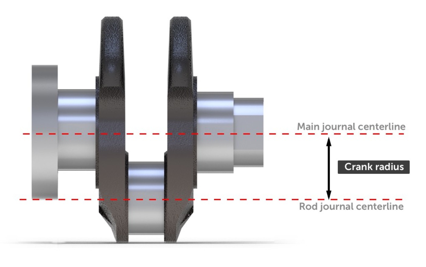
The distance between the center of the main journal and the center of the crankshaft pin is called the crank radius , also called the crank throw . This measurement determines the range of piston travel as the crankshaft rotates - this distance from top to bottom is known as the stroke . The stroke of the piston will be twice the crank radius.
The rear end of the crankshaft extends outside the crankcase and ends with a flywheel flange . This precision machined flange is bolted to the flywheel , whose heavy mass helps smooth the pulsation of the pistons firing at different times. Through the flywheel, the rotation makes its way, through the transmission and final drive, to the wheels. In an automatic, the crankshaft is is bolted to the ring gear , that carries the torque converter, passing drive into the automatic transmission. This is basically the output of the engine - and power is taken to where it’s needed: propellers for boats and aircraft, induction coils for generators, and to the road wheels in a vehicle.
The front end of the crankshaft, sometimes called the nose, is a shaft which extends beyond the crankcase. This shaft will be locked to a toothed gear which drives the valve train through a timing belt or chain [or in highly technical applications, gear sets], and a pulley which provides power through a drive belt to accessories such as the alternator and water pump.
Crankshaft parts
Main journals
The main bearing journals , or just main journals, are clamped into the engine block and it is around these journals that the engine rotates. All crankshaft journals will be machined perfectly smooth and round, and often hardened The main journals are secured into saddles, in which a replaceable bearing insert will sit. The bearing is softer than the journal, and can be replaced as it wears and is designed to absorb small amounts of contaminants, if there are any, to save damaging the crankshaft. A main bearing cap is then bolted over the journal and tightened to an exact torque specification.
[Main journal diagram with bearings and holes]
The journals run on a film of oil which is forced into the space between the journal and the bearing through a hole in the crankshaft saddle and a corresponding hole in the bearing insert. With the correct oil pressure and supply of oil, the journal and the bearing should not make contact.
Connecting rod journals
The connecting rod journals are offset from the axis of rotation, and are attached to the big ends of the pistons’ connecting rods. Confusingly, they are commonly also called crank pins or rod bearing journals . A feed of pressurised oil comes through an angled oil passage drilled from the main journal.
Some connecting rods have an oilway drilled through them to to allow oil to be sprayed onto the cylinder wall. When this is the case, the connecting rod journal bearings will have a groove to allow a feed of oil into the connecting rod.
Crankshaft lubrication
Metal-to-metal contact is the enemy of an efficient engine, therefore the main journals and rod journals both ride on a film of oil that sits on the bearing surface.
Supplying oil to the main journal bearing is easy: Oil galleries from the engine block lead to each crankshaft saddle, and a matching hole in the bearing shell allows this oil to reach the journal.
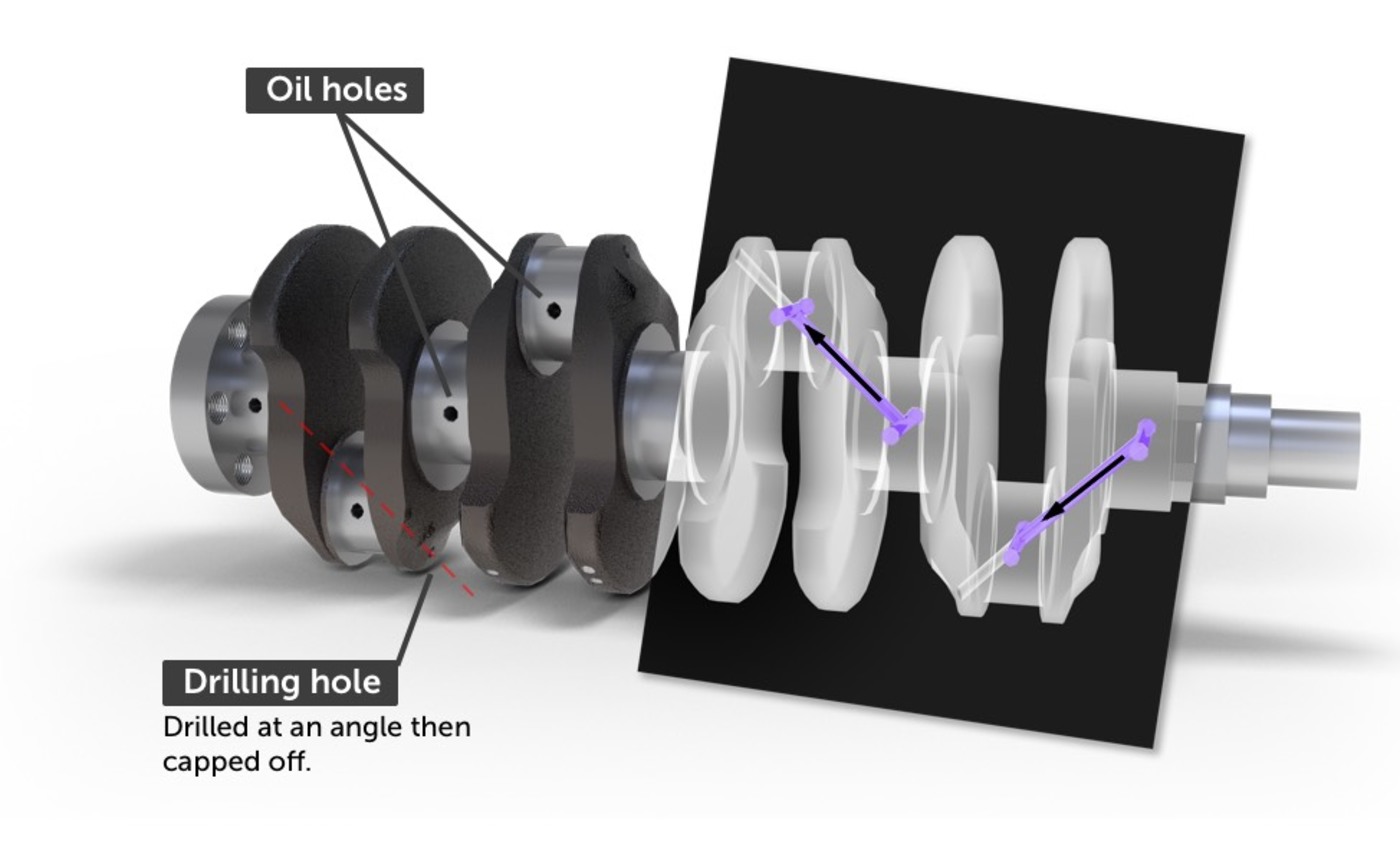
The rod journal bearings require the same lubrication but they are rotating around the crankshaft at an offset. To get the oil to these bearings, oil passageways run inside the crankshaft - through the main journal, diagonally through the web, and out through holes in the rod journals. A groove in the main rod bearing allows oil to be continually forced down the passageway to the rod journals, assisted by being flung outwards by the centrifugal force of the rotating crankshaft.
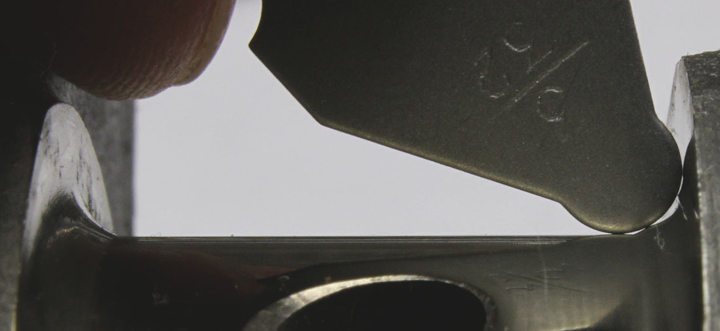
The clearances between the journals and bearings are the main source of oil pressure in the engine. If the clearances are too high then oil flows out freely, and pressure is not maintained. Clearances that are too low will cause high oil pressure and risk metal-to-metal contact. It is therefore essential that the clearance between the bearings and journals are measured when an engine is rebuilt.
Counterweights
The crankshaft is subject to strong rotational forces, and the mass of the connecting rod and piston moving up and down exerts a significant force. Counterweights are cast as part of the crankshaft to balance out these forces. These counterweights allow for a smoother running engine and higher RPM.
A crankshaft will be balanced at the factory. In this process, the flywheel is attached and the entire assembly is spun on a machine which measures where it is out of balance. Balance holes are drilled in the counterweights to reduce weight. If weight needs to be added, a hole is drilled and then filled with heavy metal or mallory. This is repeated until the crankshaft is balanced.
Crankshaft thrust washers
At some point along its length, two or more thrust washers will be installed to prevent the crankshaft moving lengthways. On the illustrated crankshaft, there are thrust washers on both sides of the central journal. These thrust washers sit between machined surfaces in the web and the crankshaft saddle - maintaining a specified small gap and minimizing the amount of lateral movement available to the crankshaft. The distance that the crankshaft can move from end-to-end is called its endplay and an acceptable range will be specified in the service manuals.
Some engines have these thrust washers formed as part of the main bearings, others, generally older types, use separate washers.
Main oil seals
Both ends of the crankshaft extend beyond the crankcase, so some method of preventing oil escaping these openings must be provided. This is the job of the two main oil seals, one at the front and one at the rear.
The rear main seal is installed between the rear main journal and the flywheel. It is commonly a synthetic rubber lip-seal. The seal is pressed into a recess between the engine block and the oil pan. The seal has a shaped lip which is held tight against the crankshaft by a spring called a garter spring.
A failed oil seal is a major problem because they are adjacent to main journals which receive, and need, a good supply of pressurised oil. Combined with the spinning of the crankshaft, this leads to rapid loss of engine oil through any breach of an oil seal.
The front oil seal is similar to the rear, although its failure is less catastrophic and it is more easily accessed. The front oil seal will be behind the pulleys and timing gear.
An oil seal itself is a cheap part, but accessing it requires a lot of labour in removing the transmission, clutch, flywheel and possibly the crankshaft. It’s therefore recommended to replace the oil seals any time the engine is dismantled and the parts are accessible.
Crankshaft layouts
The basic crankshaft shown above is from an inline 4-cylinder engine. Other crankshaft designs will depend on the engine layout. This is a topic covered in more detail in the article about engine layout. But one point of note is that in V-shaped and W engines two connecting rods may share a single rod journal. Some typical crankshaft layouts are shown below.
V6 crankshaft
A V6 crankshaft is somewhat specialist because it requires rod journals to be split to maintain an even firing interval. This necessitates the rod journals being split, or splayed, in what is known as a split-pin or split-journal design.
Faults
The crankshaft, being very sturdy, is a reliable component and crankshaft failures are rare unless an engine is subject to extreme conditions.
Worn journals
Without enough oil pressure, the crankshaft journals will make contact with the bearing surfaces gradually increasing the clearance and worsening the oil pressure. Taken to an extreme, this can lead to destroyed bearings and cause serious engine damage. Where journals are worn to below their service limits, or are no longer perfectly round, they will need to be ground as described below.
Fatigue
Constant forces on the crankshaft can lead to fatigue fractures, usually to be found on the fillet where the journals join to the web. A smooth radius of this fillet is critical to avoid weak spots leading to fatigue cracks. A crankshaft can be inspected for cracks using magnafluxing .
Modifications and Upgrades
Crankshaft grinding
Journals wear over time. They may develop a rough surface, or become out-of-round or tapered. In these cases their surface can be restored in a process called crankshaft grinding. When a crankshaft is ground its journals will be reduced in diameter and so oversized, thicker bearings will need to be installed.
Stroker crankshafts
The cylinder capacity can be increased by moving the pistons over a longer stroke. The stroke of an engine is determined by the crank radius, being the distance of the rod journals from the main journals. A crankshaft with a larger crank radius will produce a longer stroke and a greater cylinder capacity - this is known as a stroker crankshaft. Shorter connecting rods will be required when a stroker crank is installed. Otherwise the pistons could travel too high in the cylinder - causing unacceptably higher compression or impacting on the cylinder roof.
Stroker crankshafts for frequently modified engines are sold in a kit with shorter connecting rods and pistons. A stroker kit for the Mazda MX5 Miata 1.8L engine can convert it to a 2L engine at a cost of around $5,500.
Offset grinding
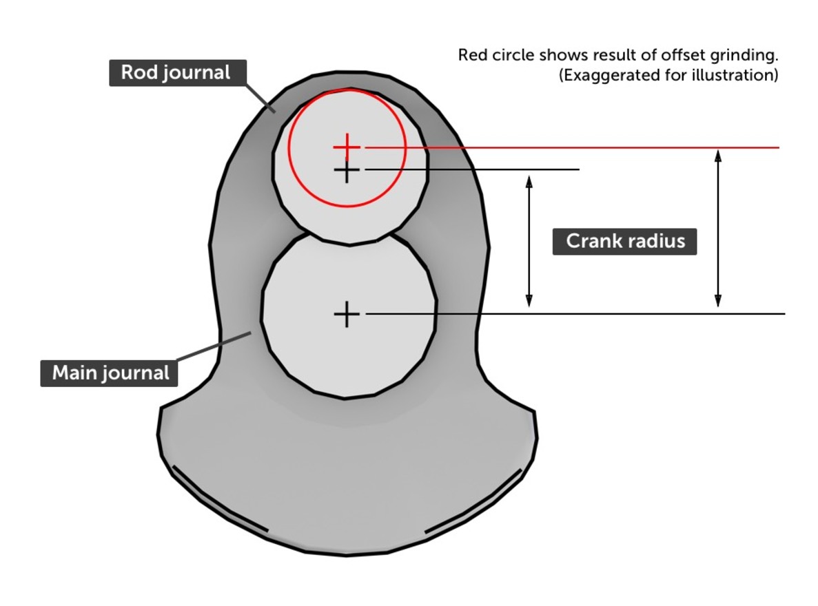
An alternative to installing a stroker crankshaft is to grind the rod journals to a smaller size, at an offset - thus moving the center of the journal away from the crankshaft centerline. This is illustrated above.
It can be seen that by moving the center of the rod journal, the crank radius has been increased leading to a longer stroke. This is specialist machining and the increase in stroke that can be achieved will depend on the thickness of the journals.
How a crankshaft is made
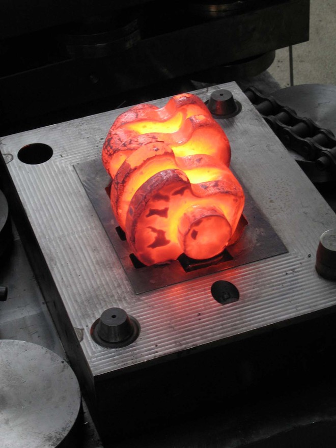
Most production engines use a cast iron crankshaft which is made by pouring molten iron into a mould. Forged crankshafts are used in some performance engines. A forged crankshaft is made by heating a block of steel until red hot, and then using extremely high pressure to form it into shape.
Once a crankshaft has been forged or cast, its journals and bearing surfaces are machined perfectly smooth. Oil passageways, or oilways, are drilled. Production engines will generally leave the webs with their original rough casting finish but performance engines will machine every part of the crankshaft to reduce oil drag.
The journals must be harder than their bearings to ensure that any wear occurs on the replaceable bearings and not the crankshaft, which should last for the lifetime of the engine. The manufacturing process will include hardening of these areas through nitriding or heat treatment.
Extremely high performance and custom crankshafts, are machined from a block of solid material, producing a billet crankshaft. Producing a one-off crankshaft by this process would cost a minimum of around $3,000 so it is reserved for competition racing and restoration situations.
Continue reading: Pistons