From our insanely detailed guide:
Pistons
The piston’s function is to act as a moveable plug in the cylinder, forming the bottom part of the combustion chamber. There’s a gas-tight seal between the piston and the cylinder wall - so the only way for the hot combustion gases to expand is by forcing the piston down. It’s the same principle behind a cannonball, but instead of flying off into someone’s beloved pirate ship, the piston is pushed back up the cylinder by the rotating crankshaft and the cycle repeats itself.
Over 60% of the friction inside the engine comes from the motion of the piston assembly, and so this is a major area of focus for improving the efficiency of engines. The piston is still seeing ongoing development and research as we’ll see in more detail shortly.
Huge forces are generated during the change in direction of a piston on its up and down motion. A lighter piston assembly has less momentum, thus exerting less force and allowing higher RPM engines. This means that there’s a constant push to reduce the weight of the connecting rod and piston.
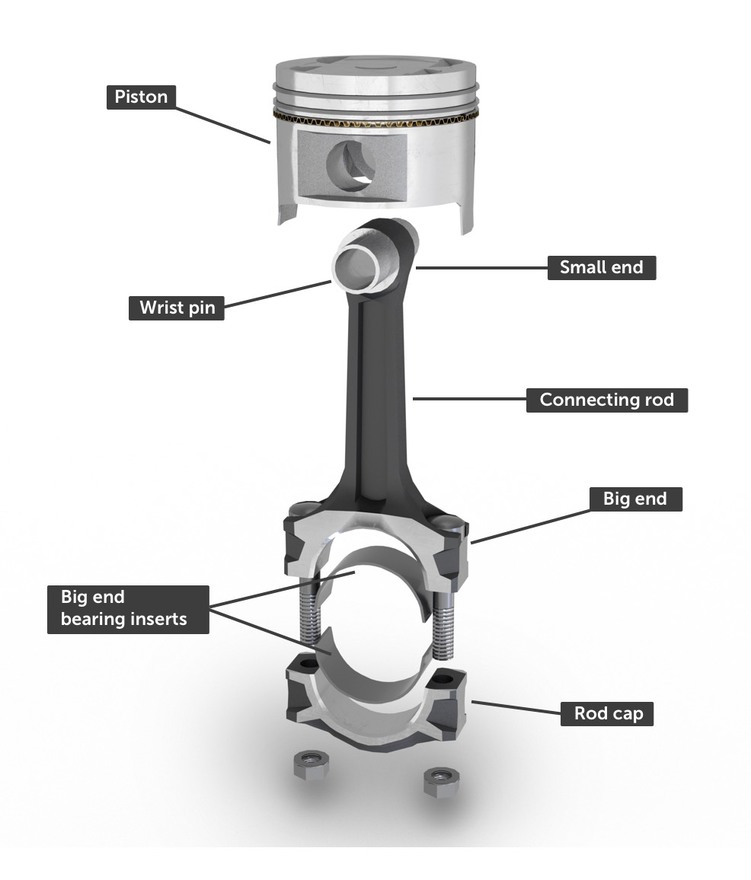
The piston is connected to the crankshaft through a connecting rod , often shortened to rod or conrod . These parts together are known as the piston assembly . Both ends of the connecting rod are free to pivot: The part of the connecting rod which connects to the piston is called the small end , and the end that attaches around the crankshaft is called the big end . The big end will have bearing inserts which minimise friction and maintain an exact oil clearance with the rod journal on the crankshaft. The connecting rod is split into two - with a rod cap being used to clamp around the big end bearing and crankshaft.
Piston assembly components
Piston
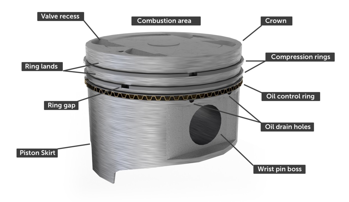
The power in an engine all comes from the force pushing on the top of the piston. That force is determined as the area of the piston multiplied by the gas pressure. Bigger pistons, and higher gas pressure will provide more power. On the whole, piston size is constrained by the design of the engine but the piston does have a vital role in maintaining high gas pressure by creating a gas-tight seal with the cylinder wall.
The top surface of the piston is called the crown (also head or dome ). There are various shapes of crown in production engines, but typically the crown will be flat, domed or dished.
[Various crown shapes]
Almost all modern pistons include valve reliefs which provide a clearance around the valves at the top of the piston stroke.
The crown, being the area directly in contact with the hot combustion gases, gets extremely hot. It is this area that expands the most and so there will be a slight taper inwards from the bottom of the piston to allow a greater clearance around this top land between the crown and top piston ring.
While we want a gas-tight seal, we also need the piston to run smoothly along the cylinder with minimal friction, so the piston needs some clearance . A typical piston will have a clearance of 0.1mm (0.004”) between itself and the cylinder wall - that’s around the width of a human hair. To maintain this clearance, the piston must be precisely machined, and the alloy that it is made from will be exactly specified to account for thermal expansion.
The small gap between the piston and cylinder wall is bridged by the piston rings , which fit into grooves on the piston in an area known as the piston belt . The spaces between these grooves are called ring lands .
The piston is attached to the connecting rod by a short hollow tube called a wrist pin , or gudgeon pin . This wrist pin carries the full force of combustion.
The piston is not only subject to vertical forces during combustion, but also side forces caused by the continuously changing angle of the connecting rod. Because of these side forces, the piston needs smooth surfaces to run against the cylinder wall and keep the piston guided vertically upright. The side surfaces of a piston are known as the piston skirt .
[Full skirt vs slipper skirt]
There are two types of skirt. The most basic is a full skirt or solid skirt, which is the classic tubular shaped piston. This design is still used on truck and large commercial engines, but has long been replaced on cars and motorcycles by a lighter design known as a slipper piston .
The slipper piston has part of the skirt cut away, leaving only the surfaces that bear on the front and back of the cylinder wall. This removal minimizes weight and reduces the area of contact between the piston and cylinder wall, thus reducing friction.
Modern production engines further reduce the friction between the piston and cylinder wall by using low-friction piston coatings , similar to teflon in a non-stick frying pan. These coatings are typically screen-printed on in a patch to the piston skirts - such as the illustrated graphite-based coating on a Ford Fiesta Ecoboost engine.
[Ford piston]
As the piston is pushed down on the combustion stroke, it will exert a sideways force in the opposite direction to the angled connecting rod. The direction of the cylinder on which this force acts is known as the thrust side, and both the piston and cylinder wall will suffer greater wear in this area.
[Diagram of thrust]
The piston gets incredibly hot, and needs to dissipate this heat efficiently. The heat from a piston goes to three places: As radiant heat into the combustion chamber, into the cylinder walls via the piston rings and down the connecting rod. Additionally, many engines cool the piston through the use of oil sprayed onto the underside.
Piston rings
The piston rings fit around the piston, bridging the small clearance between the piston and cylinder wall. There are typically three piston rings on a piston and they perform different functions.
Compression rings
The top two rings are called compression rings (also known as pressure rings or gas rings ) and their main role is to prevent gases from getting through the small clearance between the piston and cylinder wall. This passage of gas past the piston and into the crankcase is known as blowby and should be minimized to maintain compression.
Compression rings are typically made from solid cast iron and exert an outward pressure on the cylinder wall. This outward pressure comes from the natural springiness of the rings, but is supplemented on the combustion stroke by gas pressure behind the rings which pushes them more tightly against the cylinder wall.
[Gas pressure behind compression rings]
It’s important to note that the compression rings don’t exert side pressure on the piston, or act as guides for it. The groove in the piston will be deeper than the width of the piston ring, allowing the ring to run on a film of oil.
The compression rings also act to transfer heat from the piston to the cylinder wall, where it is dissipated into the coolant flowing through water jackets.
These rings are broken with a small gap which allows them to be installed and removed over the piston. The width of this piston ring gap will be specified by the manufacturer, and can be measured by placing the ring inside the cylinder and measuring the gap with a feeler gauge. The gaps are greatly exaggerated in this illustration, in reality they will be very thin - 0.2mm or less.
Oil control rings
The lower ring on a piston is an oil control ring . Oil is constantly sprayed onto the cylinder walls either from holes in the connecting rods or by jets installed in the crankcase. For minimal friction, we need an thin oil film and the function of the oil control ring is to remove excess oil and leave an ideal oil film for the compression rings and piston skirt to glide over.
We definitely don’t want oil in the combustion chamber: the presence of oil can cause poor combustion, high emissions, excess carbon buildup on the valves and piston and blue smoke - all bad news for a smooth-running engine.
The oil control ring will typically be made of two thin chrome scraper rings with a spacer sandwiched between them to allow oil be removed. It’s designed to glide over the oil on the upwards stroke, and scrape it off on the downward stroke. This is known as a segmented design. The oil control groove will have holes drilled in it to allow excess oil to easily drain back into the crankcase.
Installing new piston rings
The area of the cylinder wall above the top compression ring is not swept by the rings, and so suffers less wear. This can cause a ridge to build up over the lifetime of the engine. If new rings are installed on a cylinder that hasn’t been rebored, then a ring with a notch removed, known as a ridge dodger may be required to ensure that the new ring doesn’t make contact with this ridge of material.
[Diagram of ring offsets]
When new rings are installed, the gaps should be offset and never directly inline with each other to prevent a direct path for gases to escape.
Wrist pin
The piston is attached to the connecting rod through a hollow, hardened steel tube known as the wrist pin or gudgeon pin . This pin passes through the small end of the connecting rod and allows it to pivot on the piston.
There are two methods of securing the wrist pin. A semi-floating arrangement has the pin fixed into the connecting rod, while free to rotate in the holes in the piston. A fully-floating wrist pin will be free to rotate in both the small end and the piston, and will be secured in place using circlips, or Teflon buttons in the ends of the pin. For a fully-floating wrist pin there will be replaceable bushing inside the small end hole.
The wrist pin may be slightly offset laterally rather than exactly centered on the piston. This is known as an offset wrist pin and is used to cut down on side-to-side movement of the piston within the cylinder. Excess side-to-side movement is known as piston slap due to the knocking noise it makes.
Connecting Rod
The connecting rod carries the force from the piston to the crankshaft, it is constantly subjected to stretching, squashing and bending forces as it acts as the intermediary in this push-pull relationship. The connecting rod needs to be structurally strong and it’s no coincidence that it takes the form of a miniature steel I-beam, similar to its bigger brothers holding up skyscrapers and bridges. The I-beam profile gives a maximum of structural strength at the minimum weight cost and, like the piston, we want to keep the weight of the connecting rod as low as possible.
The strength demanded of the connecting rod mean that it is made of forged steel or powdered steel. Exotic engines may have titanium rods. Cast iron is not used due to its weight.
The top of the connecting rod that is secured to the piston is called the small-end . It won’t always have bearings. From the small end, the rod runs in an I-beam shaped profile down to the big-end which is split into two parts to allow it to fit around its crankshaft journal. The bottom part of the rod is called the rod cap and it will be secured by either studs or bolts to the rod itself.
The rod is now typically manufactured as one piece and then the rod cap scribed and broken off. This leaves an uneven finish on the mating surface, but gives greater strength. It’s essential that rod caps not be mixed up with other connecting rods - they belong together as a set.
The big end will have bearing inserts in two halves, these bearing inserts will be made of the same material as those for the main journals. The big end bearings are lubricated by oil received under pressure through passageways in the crankshaft.
Many connecting rods will have a hole drilled through them from the big end up, through the shaft, to an outlet hole somewhere along their length. This passage allows oil to pass up the connecting rod from the big end, and be sprayed onto the thrust area of the cylinder wall, where friction is at a maximum.
Faults
Piston slap
Wear in the cylinder wall or the piston skirt can lead to clearances that are too great between the piston and the cylinder wall. This allows excessive side-to-side movement of the piston. When the piston changes direction at the top and bottom of its stroke, this can cause it to knock on the cylinder wall causing a noise known as piston slap .
Piston slap will generally be worse when the engine is cold, before the piston has had time to warm up and expand. It can be cured by machining the cylinder and using an oversized piston.
Modifications and Upgrades
Uprated pistons and rods
Installing a set of stronger, lighter performance rods and pistons will create a stronger engine. This may be essential for turbocharging or supercharging an engine. Moving from forged rods to titanium or powdered (sintered) steel will result in a stronger engine.
Piston coatings
As discussed above, recently designed engines often have a low-friction coating applied at the factory to their pistons. But these coatings are also available in the aftermarket to reduce friction and increase (or decrease) heat transfer.
[Coating examples]
- Coatings are applied to the skirt to reduce friction between it and the cylinder wall.
- Ceramic coatings can be applied to the crown and are designed to reflect heat back into the combustion chamber and decrease the amount transferred into the piston.
- The underside of the piston may have a non-slip coating known as an
oil-shed coating
which repels oil, thus reducing the weight of the assembly and allowing more effective oil cooling.
Continue reading: Cylinder head