Checking and adjusting valves
The Video Course teaches you everything about modern cars.
Valve clearances are the small gaps between the tops of the valve stems and the part of the mechanism which presses on them to open the valves .
Check the clearances at regular intervals as specified in the car service schedule, and adjust if necessary. Reset the clearances whenever the cylinder head has been removed.
The job is commonly called adjusting the tappets .
A few cars have hydraulic tappets, which are self adjusting and do not need checking.
Before starting, make sure you know the type of valve mechanism commonly called valve gear - fitted to your engine , and the relative valve clearances. The car handbook should tell you the clearances - if not, consult a dealer or the car service manual.
The valve gear fitted to your engine will be either pushrod (OHV) or overhead camshaft (OHC) (See The engine - how the valves open and close ). There are two types of OHC valve gear direct acting and indirect acting.
The tappets on an OHC engine are usually adjusted by placing shims of a predetermined size under them.
That is a job best left to a garage which has a micrometer for measuring shims, and a wide selection of them. But you can check the clearances yourself, and decide whether they need adjusting.
You must know the firing order of the engine, which cylinder is No. 1, which are inlet and exhaust valves and which rockers or cams operate them. Make a plan of all this information on paper.
Find the correct valve clearances for inlet and exhaust valves, and whether they should be adjusted with the engine hot or cold.
`Hot' means that the engine must be warmed to normal working temperature, then switched off - and you must work quickly before the engine cools.
`Cold' means absolutely cold: the engine must not have run for at least six hours - check in the car handbook.
To speed up the job on most pushrod and some types of indirect-acting OHC engines there is a sequence by which you can check more than one valve at a time. But the valves of overhead-cam engines usually have to be checked singly.
Remove the air cleaner if it overhangs the rocker cover (See Air filter change ).
Tag and number the ignition leads to avoid confusion when replacing them, then remove them from the plugs, pulling the plug caps, not the leads. If the leads are clipped down and in the way, unclip them.
Note the position of any pipes, control cables and other items fastened to the rocker cover, unfasten them and move them aside.
Remove all the plugs with a plug spanner. With the plugs out, there is no compression in the cylinders, so you can turn the engine easily.
Remove the screws or bolts holding the rocker or cam cover to the cylinder head. Carefully lift the cover together with its gasket . Put the cover in a clean place, upside-down on newspaper to catch oil drips. Always fit a new gasket to the rocker or camshaft cover before refitting (See Replacing gaskets and oil seals ).
Adjusting the tappets on pushrod engines
The point in the valve-operating sequence to check a pair of valves is when another pair is 'rocking' - the brief moment when the rockers are moving in opposite directions to close the exhaust and open the inlet valve.
For example, on a four-cylinder engine when the rockers on No. 1 are rocking you can check both valves on No. 4.
Turn the engine in its normal direction of rotation by using a spanner or socket wrench on the crankshaft-pulley bolt until the two chosen rockers rock.
Most engines turn clockwise , but some Honda engines and the Triumph Acclaim engine turn anticlockwise. Consult your car handbook.
If in doubt, turn the crankshaft back a short way; but if you have gone too far, turn it on almost two more turns in the normal direction and look again.
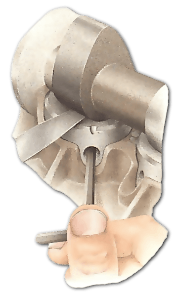
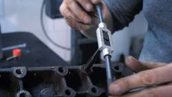
At the cylinder to be checked, insert the blade or blades of a feeler gauge , selected for the correct clearance, between the rocker and the valve system.
If the clearance is correct, the blade is a close sliding fit between the two parts. If not, it may refuse to enter the gap, or it may be a loose fit, in which case you can move the rocker up and down with the blade in place.
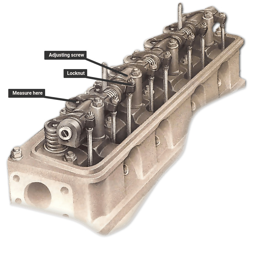
Adjust an incorrect clearance with the rocker adjuster screw. If the rockers pivot on a shaft, the screw is usually at the pushrod end.
There may be a slot-headed screw with a locknut. Use a ring spanner to loosen the locknut and turn the screw clockwise to decrease the gap, and the opposite way to increase it.
When the clearance is correct, hold the screw with a screwdriver while you tighten the locknut, then re-check the clearance.
There may be a self-locking adjusting screw with no locknut. It has a hexagonal head: adjust it with a spanner.
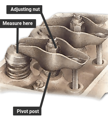
Alternatively, there may be no rocker shaft , each rocker being held by a nut on a fixed pivot post. Adjust the clearance by tightening the retaining nut to reduce the gap, or loosen it to increase the gap.
After re-checking both valve clearances, turn the crankshaft until the next pair of rockers in the sequence rocks, and repeat the check. Carry on until all the valve clearances have been checked.
Rule-of-nine method
An alternative sequence often recommended by car manufacturers for in-line four-cylinder engines, is to follow the 'rule of nine'.
There are some engines - including the Fiesta 1.1 - on which this method is not recommended: consult your car handbook or service manual if in doubt.
The feeler gauge must be a close sliding fit - with the engine hot or cold, according to the manufacturer's instructions. With many different sorts of engine layouts, No. 1 cylinder is usually at the crankshaft-pulley end, irrespective of which way the engine is mounted in the car.
Turn the engine by means of a socket spanner on the crankshaft-pulley wheel, or by jacking up one of the driven wheels, engaging a high gear, and turning the wheel by hand to turn the engine.
Removal of the sparkplugs (See Cleaning and fitting spark plugs ) will make turning the engine easier.
Count the valves of No. 1 cylinder as 1 and 2, the next pair as 3 and 4 up to the furthest pair, 7 and 8.
Turn the engine until one rocker arm is fully down, the valve being fully open.
Follow this order:
Note that whichever valve is fully down, adjust the valve which makes up to 9 when the two numbers are added.
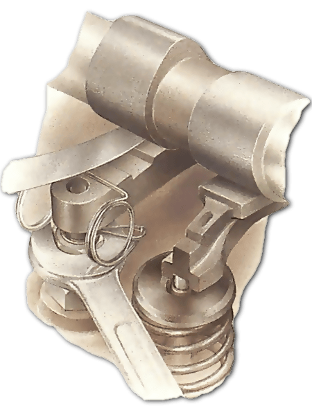
Indirect-acting overhead cam
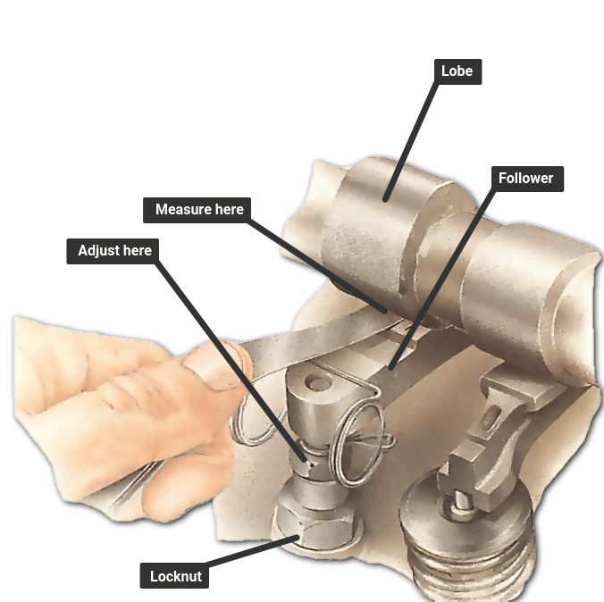
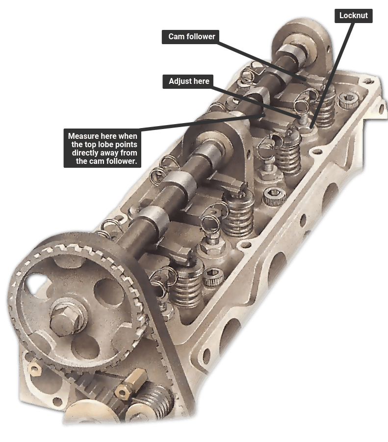
On overhead-cam engines with finger-type cam followers, measure he gap when the top of the lobe is pointing directly away from the finger. Adjust by turning the pivot post at the opposite end of the finger from the valve, hold the post to stop it turning while you slacken or tighten the locknut.
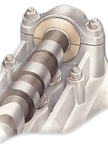
Overhead-cam engines
On overhead-camshaft engines, check the clearance of each valve when the lobe of its cam is pointing directly away from it.
Turn the crankshaft only in its normal direction of rotation, using a spanner or socket wrench on the crankshaft-pulley, to move the camshaft.
The valves come into the checking position in a jumbled order - do not mix up inlet and exhaust clearances.
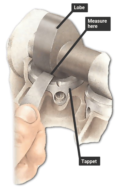
On tappets with shims, check the clearance by inserting the blade or blades of a feeler gauge between the back of the cam and the tappet.
The correct blade should be a close sliding fit in the gap. If it refuses to go in, or feels loose, try other blades to find what the gap actually is, and whether it is within the allowable limit. Any tappet clearance outside the limit should be adjusted by a garage.
However, on certain Vauxhall engines you can make small adjustments by means of screws which slide wedges under the shims: these screws are adjusted with an Allen key.
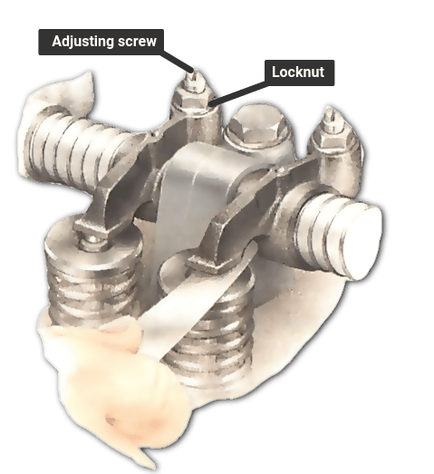
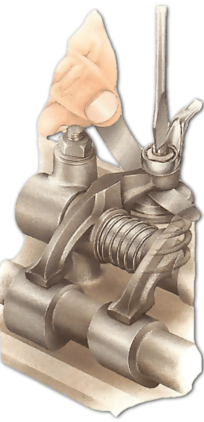
On an indirect overhead camshaft with finger-type followers (see right), check the clearance in the same way between the back of the cam and the follower.
Adjust the follower, if necessary, by screwing its pivot post up or down.
The pivot post has a locknut around its base. Hold the post with a spanner while you slacken the locknut, then turn the post anti-clockwise to reduce the clearance and clockwise to increase it.
When the gap is correct, hold the post steady while tightening the locknut, then check the clearance.
Keep turning the crankshaft until you have checked all the valves.
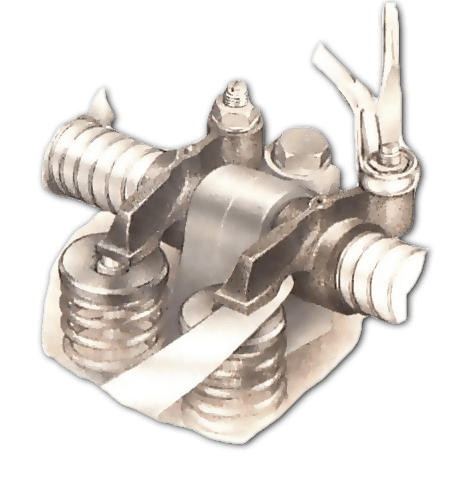
Another type of indirect-acting overhead camshaft
In a second type of indirect-acting overhead-camshaft engine, the cams bear against the ends of rocker arms.
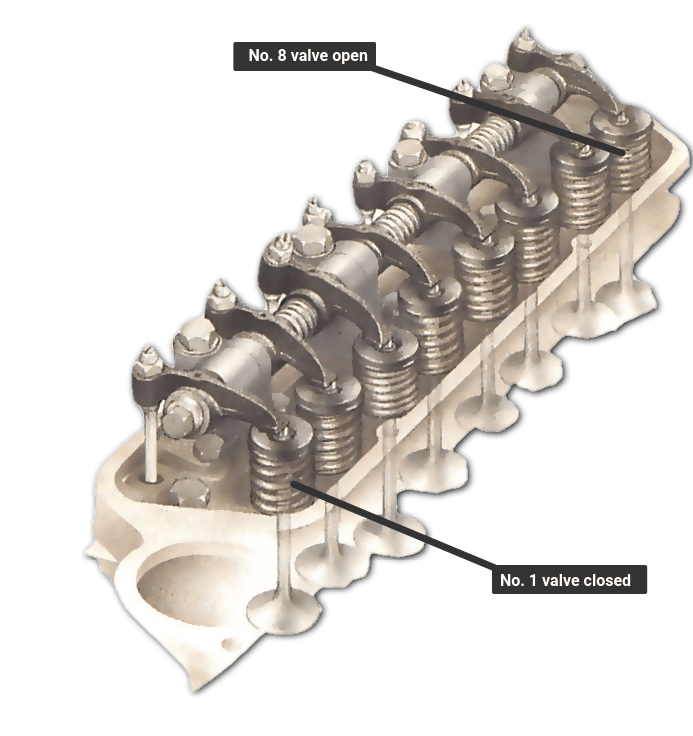
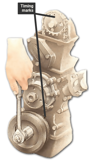
To adjust the valve clearances, use a spanner or a socket wrench on the crankshaft-pulley bolt. Turn the engine in its normal direction of rotation until No. 1 piston is at the top dead centre ( TDC ) of the compression stroke .
In that position, the TDC marks on the timing scale and the pulley line up, and there is a clearance between the rocker and valve stem of both No. 1 cylinder valves (this happens only once every two crankshaft revolutions).
Check the clearances of numbers 1, 2, 3 and 5 valves by inserting the blade or blades of a feeler gauge between the rocker and valve stem.
The clearance is correct when the gauge is a close sliding fit between the two parts.
If the clearance is wrong, either the blade cannot enter the gap or it is loose, so that you can move the rocker up and down with the blade in place.
If all these valves are correctly set, turn the crankshaft on one full turn until the TDC marks line up again, and check numbers 4, 6, 7 and 8 valves in the same way.
Adjust any incorrect clearance by slackening the locknut on the adjuster screw at the camshaft end of the rocker.

The Ultimate Car Mechanics video course
Learn everything about modern cars from our new video series.
Learn more >-
We build a Mazda MX5 Miata from scratch
We start by tearing down and then rebuilding the whole car.
-
Every part explained
There's ridiculous detail on every part. Clearly and easily explained.
-
All modeled in 3D
We've created the most detailed 3D model ever produced so we can show you everything working.
Super detailed explanations in the video course
15 hours of pro-quality, HD content with subtitles
The
video
course
Bonus: Dismantling the engine

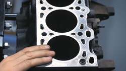
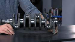
Engine Block
Crankshaft
Tools: Using a tap set
Using an engine stand

The Pistons